SolidWorks Training in Coimbatore
Solid Works training institute in Coimbatore Are you looking for a program that will help you become an expert in designing 3 d software programs? CubikCadd presents the best Solid works training centre in Coimbatore. We are the prestigious institutions for helping you draft skills in 3d CAD.
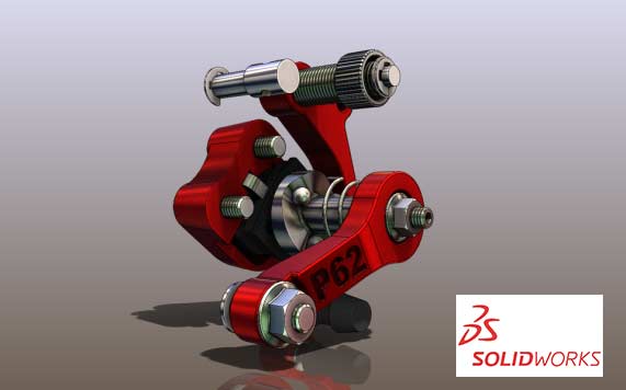
Solidworks is a tool which is used by mechanical, electrical and civil engineers. Among them, mechanical engineers use this software at the most as it has many features related to them. Solidworks is an easy learning computer-aided software which has a boom in the market nowadays and also the license copy is available at a cheaper rate. Solidworks is designed by Dassault systems.
Free Live Demo
Session
100% Successful Course Completions
Training From Professionals Experts
Fully Hands-on
Training
Certification after
Course
Solid Works Training in Coimbatore key Features
- Industry's most extensive curriculum
- The program offered online with live interactive mentoring sessions on weekends
- Learn the top skills of computer-aided designing
- Get successful career transitions
- Get a course completion certificate
- Receive placement help from experts onboard.
About Solidworks Course in Coimbatore
CubikCadd Solidworks training in Coimbatore is a practical course that teaches learners about the use and application of Solidworks. The program is computer-aided design software used to create 3d and 2d models and architecture. The software is very useful in creating architectural and commercial blueprints into 3d and 2d models. Therefore, the sole aim of this training is to teach and prepare the participants with Solidworks.
Quick Enquiry!
Course Details
Solid Works Syllabus
1.Introduction to Engineering Drawings and Design Techniques
2.Solidworks User Interface
Introduction to Solid Works
- Part Mode
- Assembly Mode
- Drawing Mode
- System Requirements
- Getting Started with Solid Works
- Menu Bar and Solid Works menus
- Command Manager
- Part Mode Command Managers
- Assembly Mode Command Managers
- Drawing Mode Command Managers
- Customized Command Manager
- Toolbar
- Pop-up Toolbar
- View (Heads-Up) Toolbar
- Shortcut Bar
- Mouse Gestures
- Dimensioning Standard and Units
- Important Terms and Their Definitions
- Feature-based Modeling
- Parametric Modeling
- Bidirectional Associativity
- Windows Functionality
- Geometric Relations
- Blocks
- Library Feature
- Design Table
- Equations
- Collision Detection
- What’s Wrong Functionality?
2D Command Line Emulator
- SimulationXpress
- Physical Dynamics
- Physical Simulation
- Seed Feature
- Feature Manager Design tree
- Absorbed Features
- Child Features
- Dependent Features
- Auto-Backup Option
- Selecting Hidden Entities
- Color Scheme
- Self-Evaluation Test
Basic Sketch and 3D Sketching
- The Sketching Environment
- Starting a New Session of Solid Works
- Work flow customization Area
- Task Panes
- Solid Works Resources Task Pane
- Design Library Task Pane
- File Explorer Task Pane
- View Palette Task Pane
- Appearances, Scenes, and Decals Task Pane
- Custom Properties Task Pane
- Starting a New Document in Solid Works
Part Assembly Drawing
- Understanding the Sketching environment
- Setting the Document Options
- Modifying the Drafting Standards
- Modifying the Linear and Angular Units
- Modifying the Snap and Grid Settings
- Learning Sketcher Terms
- Origin
- Inferencing Lines
- Select tool
- Selecting Entities Using the Box Selection
- Selecting Entities Using the Cross Selection
- Selecting Entities Using the SHIFT and CTRL Keys
- Invert Selection Tool
- Drawing Lines
- Orientation Rollout
- Options Rollout
- Drawing Continuous Lines
- Drawing Individual Lines
- Line Cursor Parameters
- Drawing Tangent or Normal Arcs Using the Line Tool
- Drawing Construction Lines or Centerlines
- Drawing the Lines of Infinite Length
- Drawing Circles
- Drawing Circles by Defining their Center Points
- Drawing Circles by Defining Three Points
- Drawing Construction Circles
- Drawing Arcs
- Drawing Tangent/Normal Arcs
- Drawing Center point Arcs
- Drawing 3 Point Arcs
- Drawing Rectangles
- Drawing Rectangles by Specifying their Corners
- Drawing Rectangles by Specifying the Center and a Corner
- Drawing Rectangles at an Angle
- Drawing Center point Rectangles at an Angle
- Drawing Parallelograms
- Drawing Polygons
- Drawing Splines
- Drawing Slots
- Creating a Straight Slot
- Creating a Center point Straight Slot
- Creating a 3 Point Arc Slot
- Creating a Center point Arc Slot
- Placing Sketched Points
- Drawing Ellipses
- Drawing Elliptical Arcs
- Drawing Parabolic Curves
- Drawing Display Tools
- Zoom to Fit
- Zoom to Area
- Zoom In/Out
- Zoom to Selection
- Pan
- Previous View
- Redraw
- Deleting Sketched Entities
- Self-Evaluation Test
EDITING AND MODIFYING SKETCHES
- Editing Sketched Entities
- Trimming Sketched Entities
- Extending Sketched Entities
- Filleting Sketched Entities
- Chamfering Sketched Entities
- Offsetting Sketched Entities
- Mirroring Sketched Entities
- Mirroring While Sketching (Dynamic Mirror Entities)
- Moving Sketched Entities
- Rotating Sketched Entities
- Scaling Sketched Entities
- Copying and Pasting Sketched Entities
- Creating Patterns
- Creating Linear Sketch Patterns
- Creating Circular Sketch Patterns
- Editing Patterns
- Writing Text in the Sketching Environment
- Modifying Sketched Entities
- Modifying a Sketched Line
- Modifying a Sketched Circle
- Modifying a Sketched Arc
- Modifying a Sketched Polygon
- Modifying a Spline
- Modifying the Coordinates of a Point
- Modifying an Ellipse or an Elliptical Arc
- Modifying a Parabola
- Dynamically Modifying and Copying Sketched Entities
- Splitting Sketched Entities
ADDING RELATIONS AND DIMENSIONS TO SKETCHES
-
<
- Applying Geometric Relations to Sketches
- Applying Relations Using the Add Relations Property Manager
- Design Intent
- Dimensioning a Sketch
- Horizontal/Vertical Dimensioning
- Aligned Dimensioning
- Angular Dimensioning
- Diameter Dimensioning
- Radius Dimensioning
- Linear Diameter Dimensioning
- Ordinate Dimensioning
- Concept of a Fully Defined Sketch
- Fully Defined
- Over defined
- Under defined
- Dangling
- No Solution Found
- Invalid Solution Found
- Sketch Dimension or Relation Status
- Deleting Over defining Dimensions
- Displaying and Deleting Relations
- Opening an Existing File
- Address Bar
- File name
- Type Drop-down List
- Open as Read-Only
- Quick view
- References
- Configurations
- Display States Area
4.Part Modeling And Advance Part Modeling
- Advanced Dimensioning Techniques Fully Defining the Sketches
- Dimensioning the True Length of an Arc
- Measuring Distances and Viewing Section Properties
- Measuring Distances
- Determining the Section Properties of Closed Sketches
- Creating Base Features by Extruding Sketches
- Creating Thin Extruded Features
- Creating Base Features by Revolving Sketches
- Creating Solid Revolved Features
- Creating Thin Revolved Features
- Determining the Mass Properties of Parts
- Dynamically Rotating the View of a Mode
- Rotating the View Freely in 3D Space
- Rotating the View around a Selected Vertex, Edge, or Face
- Modifying the View Orientation
- Changing the Orientation Using the Reference Triad
- Restoring the Previous View
- Displaying the Drawing Area in Viewports
- Displaying the Drawing Area in Two Horizontal Viewports
- Displaying the Drawing Area in Two Vertical Viewports
- Displaying the Drawing Area in Four Viewports
- Display Modes of a Model
- Wireframe
- Hidden Lines Visible
- Hidden Lines Removed
- Shaded With Edges
- Shaded
- Additional Display Modes
- Shadows in Shaded Mode
- Perspective
- Assigning Materials and Textures to Models
- Assigning Materials to a Model
- Changing the Appearance of the Model
- Editing the Appearances
ADVANCED MODELING TOOLS-I
- Advanced Modeling Tools
- Creating Simple Holes
- Creating Standard Holes Using the Hole Wizard
- Adding External Cosmetic Threads
- Creating Fillets
- Selection Methods
- Creating Fillets Using the FilletXpert
- Creating Chamfers
- Creating Shell Features
- Creating Wrap Features
ADVANCED MODELING TOOLS-II
- Advanced Modeling Tools
- Creating Mirror Features
- Creating Linear Pattern Features
- Creating Circular Pattern Features
- Creating Sketch Driven Patterns
- Creating Curve Driven Patterns
- Creating Table Driven Patterns
- Creating Fill Patterns
- Creating Rib Features
- Displaying the Section View of a Model
- Changing the Display States
EDITING FEATURES
- Editing the Features of a Model
- Editing Using the Edit Feature Option
- Editing Sketches of the Sketch-based Features
- Changing the Sketch Plane of the Sketches
- Editing by Selecting an Entity or a Feature
- Editing Using the Instant3D Tool
- Editing Features and Sketches by Cut, Copy, and Pastev
- Cutting, Copying, and Pasting Features and Sketches from One Document
- To the Other
- Copying Features Using Drag and Drop
- Deleting Features
- Deleting Bodies
- Suppressing Features
- Unsuppressing the Suppressed Features
- Unsuppressing Features with Dependents
- Hiding Bodies
- Moving and Copying Bodies
- Reordering the Features
- Rolling Back the Feature
- Renaming Features
- Creating Folders in the Feature Manager Design tree
- What’s Wrong Functionality?
ADVANCED MODELING TOOLS-III
- Advanced Modeling Tools
- Creating Sweep Features
- Creating Cut-Sweep Features
- Creating Loft Features
- Adding a Section to a Loft Feature
- Creating Lofted Cuts
- Creating 3D Sketches
- Creating Grid Systems
- Editing 3D Sketches
- Creating Curves
- Extruding a 3D Sketch
- Creating Draft Features
ADVANCED MODELING TOOLS-IV
- Advanced Modeling Tools
- Creating Dome Features
- Creating Indents
- Creating Deform Features
- Creating Flex Features
- Creating Fastening Features
- Creating the Mounting Boss
- Creating Snap Hooks
- Creating Snap Hook Grooves
- Creating Vents
- Creating a Lip/Groove Feature
- Creating Freeform Features
- Face Settings Rollout
- Control Curves Rollout
- Control Points Rollout
- Display Rollout
- Dimensioning a Part Using DimXpert
- Specifying the Datum
- Pop-up Toolbar
- Adding Dimensions
- Specifying the Location of a Feature
- Adding Geometric Tolerance to the Features
- Collecting Pattern Features
- Adding Dimensions Automatically
5.Reference Geometry and Configuration
- Importance of Sketching Planes
- Reference Geometry
- Reference Planes
- Creating New Planes
- Creating Reference Axes
- Creating Reference Points
- Creating Reference Coordinate Systems
- Advanced Boss/Base Options
- From
- End Condition
- Direction of Extrusion
- Modeling Using the Contour Selection Method
- Creating Cut Features
- Creating Extruded Cuts
- Handling Multiple Bodies in the Cut Feature
- Creating Revolved Cuts
- Concept of the Feature Scope
- Equations and Configurations
- Working with Equations
- Linking Dimensions
- Working with Configurations
- Creating Configurations by Using Design Tables
- Changing the Suppression State by Using the Design Table
- Editing the Design Table
- Deleting the Design Table
- Changing the Suppression State of a Component without Invoking the
- Design Table
- Changing the Visibility of Components in Different Configurations of an
- Assembly
6.Design Library/Library features
- Library Features
- Creating a Library Feature
- Placing Library Features in a Part
- Editing the Library Features
- Dissolving the Library Features
WORKING WITH BLOCKS
- Introduction to Blocks
- Blocks Toolbar
- Saving a Sketch as a Block in the design Library
- Creating Mechanisms by using Blocks
- Creating the Rack and Pinion Mechanism
- Creating the Cam and Follower Mechanism
- Applying Motion to Blocks
- Creating Parts from Blocks
- Selected Blocks
- Block to Part Constraint
7.Import and Export Tools
- Import Diagnostics
- Dissolve Features
- Feature recoganize
8.Sheetmetal Design
- Sheet Metal Design
- Designing the Sheet Metal Components by Creating the Base Flange
- Creating the Base Flange
- Understanding the Feature Manager Design tree of a Sheet Metal Component
- Creating the Edge Flange
- Creating Tabs
- Creating the Sketched Bend
- Creating the Miter Flange
- Creating Closed Corners
- Creating Hems
- Creating the Jog Bend
- Breaking the Corners
- Creating Cuts on the Planar Faces of the Sheet Metal Components
- Creating Lofted Bends
- Creating a Flat Pattern View of the Sheet Metal Components
- Creating Sheet Metal Components from a Flat Sheet
- Creating a Sheet Metal Component From a Flat Part
- Converting a Part or a Flat Part into Sheet Metal by Adding Bends
- Adding Bends to the Flattened Sheet Metal Component
- Unbending the Sheet Metal Part Using the No Bends Tool
- Creating a Sheet Metal Component By Designing it as a Part
- Types of Bends
- Converting a Solid Body into a Sheet Metal Part
- Designing a sheet Metal Part from a Solid Shelled model
- Ripping the Edges
- Creating Cuts in Sheet Metal Components Across the Bends
- Creating Cuts in a Sheet Metal Component Created from a Solid Model
- Creating Cuts in a Sheet Metal Component Created Using the Base Flange
- Creating Cylindrical and Conical Sheet Metal Components
- Generating the Drawing View of the Flat Pattern of the Sheet Metal Components
9.MBD Dimensioning
10.Surface Modeling
- Surface Modeling
- Creating an Extruded Surface
- Creating a Revolved Surface
- Creating a Swept Surface
- Creating a Lofted Surface
- Creating a Boundary Surface
- Creating a Planar Surface
- Creating a Fill Surface
- Creating a Radiated Surface
- Offsetting Surfaces
- Trimming Surfaces
- Untrimming Surfaces
- Extending Surfaces
- Knitting Surfaces
- Filleting Surfaces
- Creating a Mid-Surface
- Deleting Holes from Surfaces
- Replacing Faces
- Deleting Faces
- Moving and Coping Surfaces
- Mirroring Surface Bodies
- Adding Thickness to Surface Bodies
- Creating a Thicken Surface Cut
- Creating a Surface Cut
10.Weldment Design
11.Bottom Up and Top Down Assembly design
- Assembly Modeling
- Types of Assembly Design Approach
- Creating Bottom-Up Assemblies
- Placing Components in the Assembly Document
- Assembling Components
- Creating Top-down Assemblies
- Creating Components in the Top-down Assembly
- Moving Individual Components
- Moving Individual Components by Dragging
- Moving Individual Components Using the Move Component Tool
- Rotating Individual Components
- Rotating Individual Components by Dragging
- Rotating Individual Components Using the Rotate Component Tool
- Moving and Rotating Individual Components Using the Triad
- Assembly Visualization
13.Mating parts in Assembly
- Advanced Assembly Mates
- Applying the Symmetric Mate
- Applying the Width Mate
- Applying the Distance Mate
- Applying the Angle Mate
- Applying the Path Mate
- Mechanical Mates
- Applying the Cam Mate
- Applying the Gear Mate
- Applying the Rack Pinion Mate
- Applying the Screw Mate
- Applying the Hinge Mate
- Creating Sub-assemblies
- Bottom-up Sub-assembly Design Approach
- Top-down Sub-assembly Design Approach
- Inserting a New Sub-assembly
- Deleting Components and Sub-assemblies
- Editing Assembly Mates
- Replacing Mated Entities
- Editing Components
- Editing Sub-assemblies
- Dissolving Sub-assemblies
- Replacing Components
- Creating Patterns of Components in an Assembly
- Feature Driven Pattern
- Local Pattern
- Copying and Mirroring Components
- Copy a Component with Mates
- Simplifying Assemblies using the Visibility Options
- Hiding Components
- Suppressing and Unsuppressing the Components
- Changing the Transparency Conditions
- Changing the Display States
12.Exploding Assemblies
- Creating the Exploded State of an Assembly
- Creating the Explode Line Sketch
13.Evaluating Parts And Assemblies
- Checking Interferences in an Assembly
- Checking the Hole Alignment
- Creating Assemblies for Mechanism
- Analyzing Collisions Using the Collision Detection Tool
14.Detailing,BOM,And Balooning Tools
- The Drawing Mode
- Starting a Drawing Document
- Starting a New Drawing Document Using the New Solid Works Document
- Dialog Box
- Starting a New Drawing Document from the Part/Assembly Document
- Types of Views
- Model View
- Projected View
- Section View
- Aligned Section View
- Auxiliary View
- Detail View
- Broken View
- Broken-out Section View
- Crop View
- Alternate Position View
- Generating Standard Drawing Views
- Generating Model Views
- Using the View Palette to Place the Drawing Views
- Generating the Three Standard Views
- Generating Standard Views Using the Relative View Tool
- Generating Standard Views Using the Predefined View Tool
- Generating Derived Views
- Generating Projected Views
- Generating Section Views
- Generating Aligned Section Views
- Generating Broken-out Section Views
- Generating Auxiliary Views
- Generating Detail Views
- Cropping Drawing Views
- Generating Broken Views
- Generating Alternate Position Views
- Generating Drawing Views of the Exploded State of an Assembly
- Working with Interactive Drafting in Solid Works
- Editing and Modifying Drawing Views
- Changing the View Orientation
- Changing the Scale of Drawing Views
- Deleting Drawing Views
- Rotating Drawing Views
- Manipulating the Drawing Views
- Modifying the Hatch Pattern in Section Views
- Properties Rollout
- Options Rollout
WORKING WITH DRAWING VIEWS-II
- Adding Annotations to Drawing Views
- Generating Annotations Using the Model Items Tool
- Adding Reference Annotations
- Aligning the Dimensions
- Editing Annotations
- Adding the Bill of Materials (BOM) to a Drawing
- Table Template Rollout
- Table Position Rollout
- BOM Type Rollout
- Configurations Rollout
- Part Configuration Grouping Rollout
- Keep Missing Item Rollout
- Item Numbers Rollout
- Setting Anchor Point for the BOM
- Linking Bill of Materials
- Adding Balloons to the Drawing Views
- Adding Balloons using the Auto Balloon tool
- Adding New Sheets to the Drawing Views
- Editing the Sheet Format
- Creating User-Defined Sheet Formats
15.Mold and Cavity Creation using Solidworks
- Multi Body technique
- TopDown Technique
- Mold Tools
- Surface Technique
16.Solidworks routing and pipin
- Introduction About Routring and piping
- Piping and Tubing Components
- StartBy Drag/Drop
- Start at Point
- Adding Fittings
- Split Route
- Change Route Diameter
- Adding Slope
- Covering
- Routing Manager
17.Tolerance Analyst
Solidworks Motion Analysis
- 1.Basic Motion and Animation
- 2.Advance Motion tools
- 3.Results Plots and Animation
Basic Geometric Dimensioning and Tolerancing
Project: Solidworks - Bike & Scooter Disk Calliper
This is a software that lets you create and design the blueprints of 3d models basically which an engineer does later of which can be converted into files. Our experts at CubikCadd will help you learn solid work from the basics till you master in it.
Through this Solidworks course, you shall learn product design, engineering functions in Solidworks.This application lets designers quickly sketch out their ideas experiment with features and dimensions, production models and detailed drawings. The tool is used to making blueprints, concepts designing’s for Engineering, Architectural
- The course will help you design and create products
- Learn solid design modelling
- Create 3D models and precision it
- Learn advanced features in product assembly, product designing, and other related mechanisms
- Learn how to coursework during manufacturing process
- Create and render computer aided models.

I learned autocad and solidworks very well with application oriented. I felt satisfied with there teaching professionals. They educate me some core based ideas and technical knowledge's. Its very helpful for done my interviews. Thank u cubik.
I had taken solidworks and creo program in cubik cad center. It was a good experience. The faculties are highly experienced in both technical as well as software field. They taught us both technical and software knowledge. The way of teaching is very unique. I look forward to do some other courses like Ansys It was my wonderful experience in this institution .
My experience with Cubik cad is really good I am associated with mechanical CAD courses .I took two software training programme (AutoCAD+Solidworks) here and satisfied learning both . The quality of teaching and practice material provided is really upto mark .I previously learned both softwares in my college but didn't get even little about them , but after doing them in Cubik cad, I am confident working with these softwares. Trainers are really good and friendly and have desired knowledge in field of CAD/CAE.
One of The Best Institue For Couse's Just Like Autocad, Solidworks, and More.Faculty's are most Friendly and Lot's of knowledge u can Gain. Best Environment for study and Faculty's help Students anytime Anywhere. I Have Also done autocad and solidwoks with the same...
Best institute with experienced faculties. I have enrolled for creo & solidworks cubik cad gave us practical knowledge of tools along with software knowledge
Solid works Interview Questions & Answers
Solid works is a solid modelling computer-aided design (CAD) and computer aided engineering computer program that runs on Microsoft Windows. It works on the principle of parametric design which produces three interconnected files: the part, the assembly and the drawing. The solid works engineer need to have fundamental skills and concepts and good command over solid work tools. So, guys avail the opportunity in leading industries as solid works trainee, solid work design engineer, Auto cad engineer, mechanical engineer, junior mechanical engineer, etc by looking into the solid works job interview questions and answers.
Solid Works training placement in Coimbatore at Cubikcadd
Still thinking of making a switch to a Solid works designer and architect Job Role but confused about the How's and Why's & What's? So we are there! Cubikcadd Technologies provides the best solid works training in Coimbatore along with 100% placement guidance and help. We help try to figure out how to make a successful career transition into this industry.
Solid Works certification in Coimbatore
A Course completion certificate in Solid Works can let Growth in your future take wings with this switch. We are offering you a 1-click resolution to all your queries. Talk to our career experts & get all your queries answered with a Personalised plan to start a career in Solid Works.
And, more queries.......? Do not worry, We have you covered. Call us today.
Career Benefits of Solidwork Training in CubikCadd Centre Coimbatore:
- Solidworks is a tool that is made by the Dassault system and has grabbed the market globally. Every company finds this tool very easy and a quick response was given. Professionals appreciate this tool after getting experience and incorporate this tool in their firm.
- So after learning this Solidworks Course Online, a candidate has a wide opening in the market as there are lots of jobs available. If a candidate wants to start his/her manufacturing unit then he is almost on the right track to creating his design.
- Solid works certification CSWA (Certified SOLIDWORKS Associate) is given to the students and professionals who are interested to undergo solid works course and certification. This is valuable to get the job as a designing engineer or analysis in many engineering companies. Course certification provides opportunities in the market for multiple designing engineers, manufacturing companies, animation, and gaming offers jobs along with understanding the designing concepts reduce in designing time, making effective design layouts and reduce scrap rate in manufacturing companies by using prototype methods.
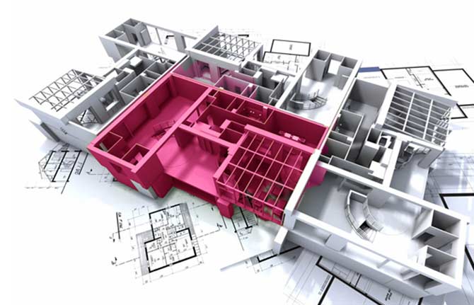
- Architectural designs can make their layouts and models in solid works environment quickly and use the exporting old design components and parts into new once by importing and making slight changes. Solid works are best suitable for interior and exterior designing with suitable visual realistic material colors and material properties usage which makes the design look more realistic and impresses viewers while presenting.
Frequently Asked Questions:
- Basic Design Knowledge
- Knowledge To Understand Engineering Drawings ,Circuits and Layouts
- Basic Knowledge In AutoCad
Solidworks is used by designers, engineers and manufacturer's to produce realistic 3d models for documentation, visualization and production.
We can A Get A knowledge to Develop Parts In 3D.Its Very Useful to Built a Assembly with some Basic Motion.By Using 3D We Will get A detailed Knowledge about Our Product.More over in India especially In Tamilnadu most of the industries are Using Solidworks for their Product Development.So We can Easily get a job anywhere
After Finishing Solidworks u can go for a job.After one years in Your Design Job u can go for Some Simulation cources like Ansys in our CUBIC cad Center.or Else If you Need a job in overseas or ouside Tamilnadu u an go for other courses like Creo,inventor which courses are offered in our Center
Yes we will surely suggest u some vacancies and Also guide to get a job in reputed industries
- All type of Mechanical Product making Industries
- Tool and Die and Press Tool making Industries
- mold Industries
- Aerospace & Defence
- Agricultural machinery
- Alternative energy
- Automotive & Transport
- Construction
- Consumer. product design
- Engineering. services
- Electronics
Latest Courses
- Mechanical CAD
- AutoCAD
- SolidWorks
- CREO/ PRO- E
- Auto Desk Inventor
- CATIA
- ANSYS
- Unigraphics NX
- Civil CAD-Modeling
- AutoCAD
- Autodesk Revit
- Auto CAD Civil 3D for Survey
- Auto Desk 3DS Max
- Bentley STAAD. Pro
- Civil ANSYS
- ETAB
- Tekla
- Electrical AutoCAD
- CNC Training
- Mastercam Training
- Revit MEP
- Rhino 3D CAD
- HVAC
Authorized SolidWorks Certificate