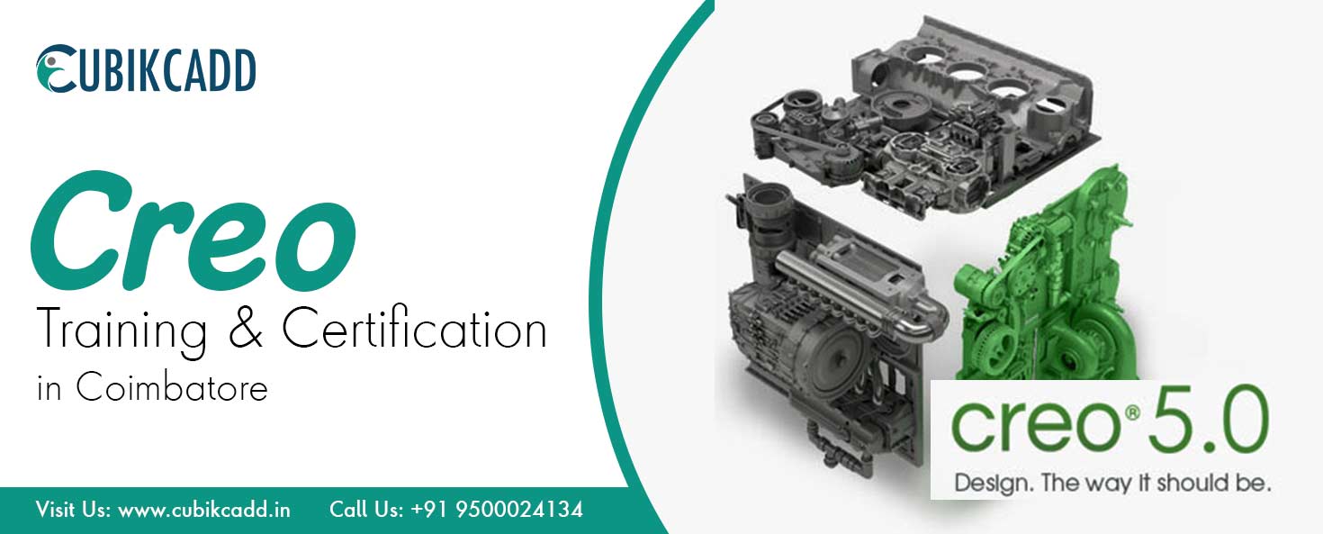
Creo Training in Coimbatore
CubikCadd is a great place to upskill in creo. We offer the best creo training in coimbatore. Our leading industry experts will train you in-depth about creo and its related software. We provide a self-paced learning environment for every individual. It’s the perfect time to invest in your 3D modeling creation expertise! Boost your 3D CAD software skills today.
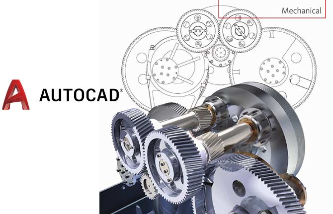
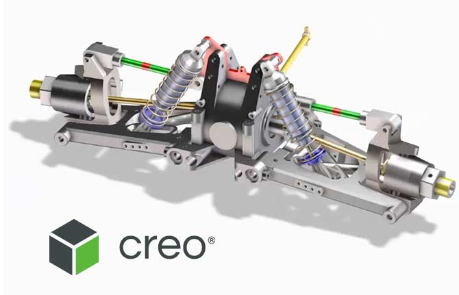
Creo is a sound foundation software that allows its user’s solid modeling, CAD, CAM and CAE along with the ability to expand deeper functionality with each component. It is the direct modeling application of a suite of 10 that consists of apps, each delivering a distinct set of capabilities for a user role within product development. Tools provided are collaborative Solid models, assemblies, Orthographic and isometric views in 2D, finite element analysis, Nonuniform rational basis spline (NURBS) surface modeling, parametric modeling, direct drafting, and NC and tooling functionality for Production and mechanical designers.
Free Live Demo
Session
100% Successful Course Completions
Training From Professionals Experts
Fully Hands-on
Training
Certification after
Course
Creo Training in Coimbatore key Features
- Industry experts onboard
- The FASTEST way to learn is taught here
- LIVE answers to YOUR most pressing questions
- Course completion certificate
- 24/7 job support and assistance
- Live projects and real case scenarios handling
- Fast-paced learning environment.
About Creo Course in Coimbatore
Creo is a group of a Computer-helped outline (CAD) composed and created by PTC. Creo underpins Product plan for discrete makers. The bundle comprises applications each conveying an unmistakable arrangement of abilities for a client part inside item advancement. The establishment of our CubikCadd Creo Training Institute in Coimbatore is in the view of the current Industrial necessities that will assist learners with getting the occupations in Top MNCs and accomplishes their objectives.
Quick Enquiry!
Course Details
Creo Syllabus
1. Introduction to Engineering Drawings
2.Creo Basic Parametric Concepts
- Introduction to Creo Parametric
- Feature-Based Nature
- Bidirectional Associative Property
- Parametric Nature
- System Requirements
- Getting Started with Creo Parametric
- Important Terms and Definitions
- File Menu Options
- Managing Files
- Menu Manager
- Model Tree
- Understanding the Functions of the Mouse Buttons
- Ribbon
- Toolbars
- Navigator
- Creo Parametric Browser
- Appearance Gallery
- Rendering in Creo Parametric
- Colour Scheme Used in this Book
3.Creating Sketch Geometry
- The Sketch Mode
- Working with the Sketch Mode
- Invoking the Sketch Mode
- The Sketcher Environment
- Working with a Sketch in the Sketch Mode
- Drawing a Sketch Using tools available in the Sketch Tab
- Placing a Point
- Drawing a Line
- Drawing a Centreline
- Drawing a Geometry Centreline
- Drawing a Rectangle
- Drawing a Circle
- Drawing an Ellipse
- Drawing an Arc
- Dimensioning the Sketch
- Converting a Weak Dimension into a Strong Dimension
- Dimensioning a Sketch Using the Normal Tool
- Dimensioning the Basic Sketched Entities
- Linear Dimensioning of a Line
- Angular Dimensioning of an Arc
- Diameter Dimensioning
- Radial Dimensioning
- Dimensioning Revolved Sections
- Working with Constraints
- Types of Constraints
- Disabling Constraints
- Modifying the Dimensions of a Sketch
- Using the Modify Button
- Modifying a Dimension by Double-Clicking on it
- Modifying Dimensions Dynamically
- Resolve Sketch Dialog Box
- Deleting the Sketched Entities
- Trimming the Sketched Entities
- Mirroring the Sketched Entities
- Inserting Standard/User-Defined Sketches
- Drawing Display Options
CREATING SKETCHES IN THE SKETCH MODE-II
- Dimensioning the Sketch
- Dimensioning a Sketch Using the Baseline Tool
- Replacing the Dimensions of a Sketch Using the Replace Tool
- Creating Fillets
- Creating Circular Fillets
- Creating Elliptical Fillets
- Creating a Reference Coordinate System
- Working with Splines
- Creating a Spline
- Dimensioning of Splines
- Modifying a Spline
- Writing Text in the Sketcher Environment
- Rotating and Resizing Entities
- Importing 2D Drawings in the Sketch Mode
CREATING BASE FEATURES
- Creating Base Features
- Invoking the Part Mode
- The Default Datum Planes
- Creating a Protrusion
- Extruding a Sketch
- Revolving a Sketch
- Understanding the Orientation of Datum Planes
- Parent-Child Relationship
- Implicit Relationship
- Explicit Relationship
- Nesting of Sketches
4.Parts Creation Using Extrude,revolve And Ribs
- Creating a Protrusion
- Extruding a Sketch
- Revolving a Sketch
- Creating Cuts
- Removing Material by Using the Extrude Tool
- Removing Material by Using the Revolve Tool
- Understanding Ribs
- Creating Trajectory Ribs
- Creating Profile Ribs
OPTIONS AIDING CONSTRUCTION OF PARTS-II
- Introduction
- Creating Feature Patterns
- Uses of patterns
- Creating Patterns
- Deleting a Pattern
- Copying Features
- New Refs
- Same Refs
- Mirror
- Move
- Select
- Mirroring a Geometry
- Creating a Section of a Solid Model
- Work Region Method
ADVANCED MODELING TOOLS-III
- Advanced Modeling Tools
- Toroidal Bend
- Spinal Bend
- Warp
- Transform Tool
- Warp Tool
- Spine Tool
- Stretch Tool
- Bend Tool
- Twist Tool
- Sculpt Tool
5. Parts Creation Using Sweep and Blend Tool
- Other Protrusion Options
- Sweep Features
- Creating Sweep Protrusions
- Aligning a Sketched Trajectory to an Existing Geometry
- Creating a Thin Sweep Protrusion
- Creating a Sweep Cut
- Blend Features
- Parallel Blend
- Rotational Blend
- General Blend
- Using Blend Vertex
- Shell Feature
- Creating a Constant Thickness Shell
- Creating a Variable Thickness Shell 8
- Datum Curves
- Creating a Datum Curve by Using the Curve Button
- Creating a Datum Curve by Sketching
- Creating a Curve by Using the Intersect Option
- Creating a Curve by Using the Project Option
- Creating a Curve by Using the Wrap Option
- Creating Draft Features
6.Modifying Parts by Using Rounds, Chamfer and Drafts
- Options Aiding Construction of Parts
- Creating Holes
- The Hole Dashboard
- Important Points to Remember While Creating a Hole
- Creating Rounds
- Creating Basic Rounds
- Creating a Variable Radius Round
- Points to Remember While Creating Rounds
- Creating Chamfers
- Corner Chamfer
- Edge Chamfer
7.Section Sweep,Helical Sweep & Swept Blends
- Advanced Feature Creation Tools
- Variable Section Sweep Using the Sweep Option
- Swept Blend
- Helical Sweep
- Blend Section to Surfaces
- Blend Between Surfaces
8.Creating Datum Features
- Datums
- Default Datum Planes
- Need for Datums in Modeling
- Selection Method in Creo Parametric
- Datum Options
- Datum Planes
- Creating Datum Planes
- Datum Planes Created On-The-Fly
- Datum Axes
- Datum Points
9.Layers, Family Table and UDF
10.Assembling Using basic and Advance Constrains
- Assembly Modeling
- Important Terms Related to the Assembly Mode
- Top-down Approach
- Bottom-up Approach
- Placement Constraints
- Package
- Creating Top-down Assemblies
- Creating Components in the Assembly Mode
- Creating Bottom-up Assemblies
- Inserting Components in an Assembly
- Assembling Components
- Displaying Components in a Separate Window
- Displaying Components in the Same Window
- 3D Dragger
- Applying Constraints
- Status Area
- Placement Tab
- Move Tab
- Packaging Components
- Creating Simplified Representations
- Redefining the Components of an Assembly
- Reordering Components
- Suppressing/Resuming Components
- Replacing
- Assembling Repeated Copies of a Component
- Modifying the Components of an Assembly
- Modifying Dimensions of a Feature of a Component
- Redefining a Feature of a Component
11.Exploding Assemblies
- Creating the Exploded State
- References Tab Offset Tab
- Explode Line Tab
- The Bill of Materials
- Global Interference
- Pairs Clearance
12.Surface Features
- Surface Modelling
- Creating Surfaces in Creo Parametric
- Creating an Extruded Surface
- Creating a Revolved Surface
- Creating a Sweep Surface
- Creating a Blended Surface
- Creating a Swept Blend Surface
- Creating a Helical Sweep Surface
- Creating a Surface by Blending the Boundaries
- Creating a Variable Section Sweep Surface Using the Sweep Tool
- Creating Surfaces, the Using the Style Environment of Creo Parametric
- Style Dashboard
- Surface Editing Tools
- Mirroring the Surfaces
- Merging the Surfaces
- Trimming the Surfaces
- Creating the Fill Surfaces
- Creating the Intersect Curves
- Creating the Offset Surfaces
- Adding Thickness to a Surface
- Converting a Surface into a Solid
- Creating a Round at the Vertex of a Surface
- Freestyle modelling environment
- Freestyle Dashboard
13.Creating Drawing views and Details
- The Drawing Mode
- Generating Drawing Views
- Generating the General View
- Generating the Projection View
- Generating the Detailed View
- Generating the Auxiliary View
- Generating the Revolved Section View
- Generating the Copy and Align View
- Generating the 3D Cross-Section View
- Editing the Drawing Views
- Moving the Drawing View
- Erasing the Drawing View
- Deleting the Drawing View
- Adding New Parts or Assemblies to the Current Drawing
- Modifying the Drawing Views
- Changing the View Type
- Changing the View Scale
- Reorienting the Views
- Modifying the Cross-sections
- Modifying Boundaries of Views
- Adding or Removing the Cross-section Arrows
- Modifying the Perspective Views
- Modifying Other Parameters
- Editing the Cross-section Hatching
DIMENSIONING THE DRAWING VIEWS
- Dimensioning the Drawing Views
- Show Model Annotations Dialog Box
- Adding Notes to the Drawing
- Adding Tolerances in the Drawing Views
- Dimensional Tolerances
- Geometric Tolerances
- Editing the Geometric Tolerances
- Adding Balloons to the Assembly Views
- Adding Reference Datums to the Drawing Views
- Modifying and Editing Dimensions
- Modifying the Dimensions Using the Dimension Properties Dialog Box
- Modifying the Drawing Items Using the Shortcut Menu
- Cleaning Up the Dimensions
OTHER DRAWING OPTIONS
- Sketching in the Drawing Mode
- Modifying the Sketched Entities
- User-Defined Drawing Formats
- Retrieving the User-Defined Formats in the Drawings
- Adding and Removing Sheets in the Drawing
- Creating Tables in the Drawing Mode
- Generating the BOM and Balloons in Drawings
14. Component Interfaces
15.Flexible Components
16. Using Assembly Features and Shrink-wrap
17.Creating Skeletons
18.Sheetmetal Design
- Introduction to Sheet metal
- Invoking the Sheet metal Mode
- Introduction to Sheet metal Walls
- Creating the Planar Wall
- Creating the Unattached Revolve Wall
- Creating the Unattached Blend Wall
- Creating the Unattached Offset Wall
- Creating Reliefs in Sheet metal Components
- Creating a Flat Wall
- Creating a Twist Wall
- Creating an Extend Wall
- Creating a Flange Wall
- Creating the Bend Feature
- Creating the Unbend Feature
- Creating the Bend Back
- Conversion to Sheet metal Part
- Creating Cuts in the Sheet metal Components
19.Display Styles and Views
Basic Geometric Dimensioning and Tolerancing
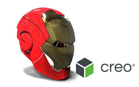
Project: CREO - IRON MAN MASK
Creo is a 3d software tool that helps you plan, design and execute various 3D product designs. It consists of various interfaces for design of 3D modelling structures. Our experts at Creo will help you learn Creo from the basics till you master in it.
- You will learn the basics and workflow of modelling
- Training to learn the process, and design the problems
- Make use of various tools in the software
- Improve your skills in core modelling of problems
- Efficiently handle real case scenarios
- Explore designing structures in 3d CAD software
- Learn assembly drawing.

I have completed my AUTOCAD and CREO software training from Cubik cad Cubik cad is the one of the best training institute for all course which is available there .What I specially like about Cubik cad is that all the faculties are with high knowledge and have a good ability to teach and make us understand well.
Here in cubik cad we can get all training or coaching like AUTOCAD , SOLIDWORK , CATIA , ANSYS and many others courses.Teaching staff is well qualified and trained well.I have Completed My AutoCAD And Creo course
Great Institute having highly qualified trainers. I have completed my solidworks and creo training in Cubik cad! And Happy that i got true knowledge about both and how to deal with it at both softwares practical lab as well as industry basis.
I have joined the course for AutoCAD, solidworks and creo I learned the course well understood the course trainer are helpful clear the doubts good institute
I did my auto CAD and CREO in this centre and now I completed , here teaching was so good, the way they are teaching is really awesome.They provided Live Projects,customized Manual and placement training
Creo Interview Questions And Answers
If you are preparing Pro-E interview and not sure which questions are likely asked in interview, we suggest you to go through Cubik Cadd interview questions and answers page to crack your job interview. Pro-E stands for Pro/ENGINEER. It is a parametric solution for 3D CAD, developed by Parametric Technology Corporation. This software is used for design, analysis and manufacturing. Civil students use the CAD software and very useful to site engineers. Strong technical skills are needed as there is huge competition. Below is the list of frequently asked Pro-E interview questions and answers which gets you ready to face the interviews:
Creo training placement in Coimbatore at Cubikcadd
Whichever training methodology you prefer, we will guide you through the foundations of advanced creo skills by explaining concepts and prerequisites to become the best. Once you have the foundations in place, you’ll have the chance to work through real interview problems. Get started with this creo training in Coimbatore, gain the confidence to handle any problem, and land your dream job with ease.
Creo certification in Coimbatore
CubikCadd gives you a chance to boost your career and take it to the next professional level by learning new skills and expanding your horizons about Creo. We offer the best creo training in Coimbatore with live certification courses and start learning the industry’s most valuable skills today!
And, more queries.......? Do not worry, We have you covered. Call us today.
Career Benefits of Cubikcadd Creo Training Institute in Coimbatore:
- Drive Freestyle geometry parametrically with the presentation of another Align capacity inside Freestyle, Creo Parametric clients would now be able to make and drive their freestyle, adapted outlines parametrically. Clients can interface their Freestyle geometry to other outer geometry with positional, digression, or typical conditions.
- Chordal/steady width rounds Chordal rounds can take out the dull procedure of constructing round geometry utilizing surfacing systems.
- After training from our Creo Training Institute in Coimbatore, you will be able to upgrade realistic execution and quality Creo Parametric keeps on observing the huge change in illustrations execution and ability.
- Unparallel Multi-CAD information dealing with capacities as well as having the capacity to import unbiased document groups (e.g., STEP, IGES, DXF, and so on.) straightforwardly into PTC Creo Parametric, clients would now be able to both import and open CATIA, SolidWorks, and Siemens NX records without the requirement for a different interpreter or access to the local writing programming.
- We are known as the best Creo Training Institute in Coimbatore. Broad equipment libraries Creo Parametric incorporates a rich and broad library of the clasp with a straightforward and natural UI to accelerate the way toward adding standard equipment to your get together outline. Notwithstanding gathering the equipment, the framework will naturally make the fitting leeway gaps in the parts for you too, where proper.
- With our Creo Training Institute in Coimbatore, Propelled bolster for designs Usage of geometry design and essentially enhances general efficiency. Likewise, clients would now be able to reference design includes that have been put on an example occurrence, instead of expecting to dependably put the highlights on the references of the example pioneer.
Frequently Asked Questions:
- One or two year Industrial Experience In design Field
- Other Basic CAD software Knowledges for easily understanding Creo
If you Want to get a job in india or Overseas U can go for Creo.More ever If you Want much Knowledge you Can go for it,Especially All Automobile Industries Are using Creo To Develop their Products
Yes we will surely suggest u some vacancies and Also guide to get a job in reputed industries.
- Mechanical Industries Which develops Valves,Autombile Parts
- Automobile Industries
- Aeronautical Industries
Latest Courses
- Mechanical CAD
- AutoCAD
- SolidWorks
- CREO/ PRO- E
- Auto Desk Inventor
- CATIA
- ANSYS
- Unigraphics NX
- Civil CAD-Modeling
- AutoCAD
- Autodesk Revit
- Auto CAD Civil 3D for Survey
- Auto Desk 3DS Max
- Bentley STAAD. Pro
- Civil ANSYS
- ETAB
- Tekla
- Electrical AutoCAD
- CNC Training
- Mastercam Training
- Revit MEP
- Rhino 3D CAD
- HVAC